Powering Up the track for DCC
I’ve decided to do a pretty simple DCC wiring construction without bothering with circuit breakers, a separate accessory bus or booster circuits. If my layout was larger or more complex, that might be something I’d have to consider. The down side is that a short will cut the supply to everything.
Since I went simple, effectively all a needed to do is ensure all the rails are suitably live using a series of ‘dropper’ wires connected onto 2 larger DC supply wires. I used brown and blue to differentiate the polarity.
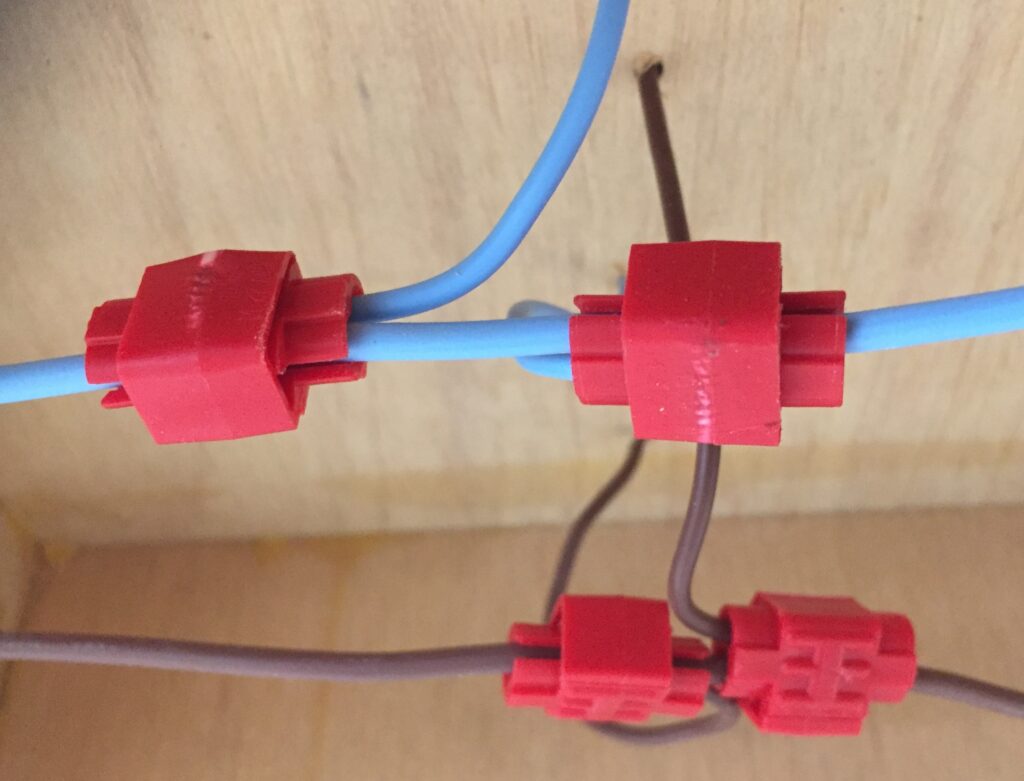
The image below shows how I connected the droppers going up through the baseboard to the main power using some 3M Scotchlock connectors. Make sure you pick the connector to march your wiring size. I could have soldered these but frankly I didn’t fancy trying to do that underneath the baseboard.

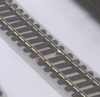
I soldered the droppers before I placed the track so I didn’t need to try and do that in-situ. There are detailed videos of ways to do this but I basically cut off the plastic under the rail, slid back the sleepers. When the rail is exposed I then soldered underneath to hide the join. Here’s a close up:

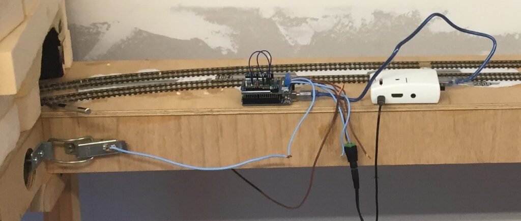
As far as getting power to the track, I initially used a simple DC speed controller off eBay and spare laptop power supply. That allowed me to test the basic circuit and to get the power to flow between the baseboards. I used also the clip connections as the conduit. Note this might not work well for larger layouts but works fine for me. For the full DCC functionality, I used an Arduino and Raspberry Pi. I show this below in prototype form loosely connected to the clips.

I’ll go into more detail on this in another post.

